Project Introduction
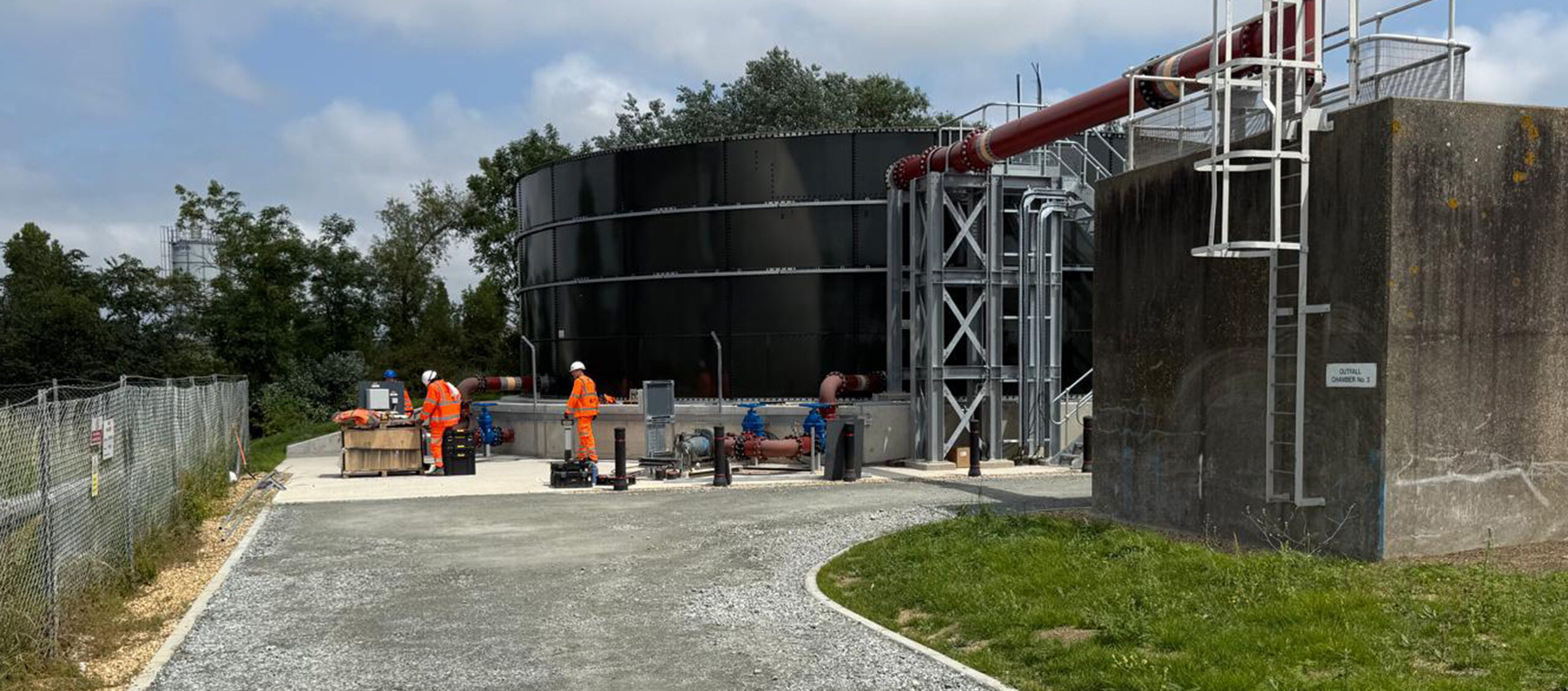
Coleman Construction & Utilities Limited successfully delivered a major civil engineering package as part of the upgrade to the Gravesend Wastewater Treatment Works (WTW) in Kent.
Appointed as a subcontractor to the Costain/MWH Delivery Partnership (CMDP JV), and working on behalf of Southern Water, the project was completed to a high standard with a contract value of £2.4 million.
This scheme formed a key element of Southern Water’s wider infrastructure improvement programme, aimed at enhancing environmental compliance and significantly increasing stormwater storage capacity. All works were completed and handed over on time, meeting Southern Water’s critical March 2025 regulatory milestone.
Project Deliverables – Civil Engineering Scope
Coleman Construction & Utilities Limited was responsible for delivering a comprehensive civil engineering scope, which included the following key deliverables:
Excavation & Earthworks:
- Bulk excavation and site preparation for new infrastructure.
- Material handling, grading, and ground remediation where required.
- Initial enabling works completed across the site to allow access for the CMC piling rig to reach all designated piling areas.
Concrete Structures:
- Construction of reinforced concrete bases, walls, and slabs to support new treatment assets.
- Works included:
- Storm Tank Structure:
- 450mm thick circular storm storage tank base with a 5° fall to central hopper.
- Retaining wall constructed around the storm tank.
- Footpaths and hardstanding areas installed for access.
- Pipework Support Structures:
- Slabs and plinths constructed to accommodate pipework, gantries, and walkways.
- Flow Meter Chamber:
- A rectangular, below-ground chamber constructed to house the new return-to-work flow meter.
- Pump Station (LVA 11 Area):
- 4m deep manhole built on a reinforced concrete base using circular shuttering.
- Retaining walls installed around the station to manage higher ground levels.
- Footpaths and hardstanding areas constructed for full site access.
- A bottom-entry MCC base was formed to accommodate new ducting and control panels.
- Storm Tank Structure:
Formwork, Reinforcement & Concrete Pouring:
- In-house delivery of all shuttering, steel reinforcement, and concrete pours.
- Ensured structural durability and compliance with design specifications.
Pipework & Ducting Installation:
- Installation of below-ground pipework and ducting in compliance with Southern Water specifications:
- 20m of DN450 ductile iron (DI) pipe from flow split chamber to new pump station.
- 185m of DN400 DI pipe from the new storm pumping station to the new storm storage tank.
- 67m of DN200 DI pipe to the existing RAS via the new flow chamber, including a 300mm diameter, 1200mm-deep core through an existing N800 pipe support beam.
- Hot tap drilling of DN200 pipework carried out by Swan Pipe Lines to maintain continuous site operation.
- Ducting System:
- Installation of five 1500x1500mm cable pits.
- 300m of 4-way 150mm ducting installed for electrical and control systems.
Manhole & Chamber Construction:
- Installation of both precast and in-situ concrete manholes and valve chambers.
- Access structures constructed to facilitate maintenance and operations.
Temporary Works & Enabling Works:
- Design and execution of temporary works, including:
- Trench support systems for 4m deep pumping station excavations.
- Sheet and frame solution provided by Groundforce for safe installation.
Access Roads & Hardstanding:
- Construction of both temporary and permanent access roads.
- Installation of hardstanding areas and working platforms to support plant operations, material delivery, and safe movement around the site.
- Reinstatement of 200m of palisade fencing that was removed to enable the construction of the new tank and pipe work.
Challenges and Solutions
- There was a large amount of muck away and aggregate imported for the initial stages of the project for installation of piling mats and haul roads. In excess of 400 loads of material was imported and 300 loads were carted away.
- Careful planning was required around the pile locations where existing services were present. Following the excavation of trial holes, design modifications were made to incorporate pipe bridges, ensuring that piling operations did not interfere with or damage existing services.
- Japanese knotweed was identified on site and was excavated and segregated in accordance with relevant environmental guidelines. Affected areas were cordoned off to prevent cross-contamination. Upon reinstatement, the works were carried out under environmental supervision and with appropriate controls to ensure no further spread or contamination occurred.
- The project was delivered on a tight schedule and successfully completed by the regulatory deadline of March 25. Although we were not initially awarded the contract, we were able to rapidly mobilise and step in to support the client, ensuring the works were completed within the challenging time constraints.
Benefits
- Coleman Construction & Utilities Limited provided a non-confrontational approach to commercial and contractual matters, preferring to work collaboratively in the interests of the project. As a result, working relationships with the client at all levels and across all disciplines are at an all-time high.
- Collaborative working has become a daily norm for Coleman Construction & Utilities staff. We always offer a solution-based approach.
- We are always striving for best practice working especially where health, safety and wellbeing are concerned – we aim for zero harm every day.
- We take pride in our work and aim to leave our sites snag free. Our attention to detail is second to none.

